VectorCADBuy now

Module · included in every plan

VectorMEP
HVAC & piping design, inside your CAD.

Route ducts and pipes with real fittings, calculate and size the network, check clashes and export IFC4 — without leaving VectorCAD and without proprietary objects in your DWG.

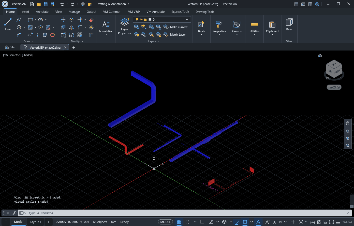
VectorMEP-phase0.dwg — VectorCAD
A ventilation and heating network in VectorCAD's shaded 3D view, with the VM Common, VM V&P and VM Annotate ribbon tabs

From route to report in five commands

Everything lives on three ribbon tabs: VM Common, VM V&P and VM Annotate.

  1. 1VMDUCT / VMPIPE

    Draw the route. Fittings, tees and reducers appear as you click, in true size and in 3D.

  2. 2VMINSTALL

    Place terminals, dampers, radiators and equipment from the product library.

  3. 3VMCALC

    Calculate flows, pressure drops, fan or pump pressure and balancing.

  4. 4VMSIZE

    Apply the recommended sizes to the whole network in one step.

  5. 5VMCLASH · VMBOM · VMIFC

    Check clashes, list quantities and hand over an IFC4 model.

Capabilities

Engineering data travels with each part, so the network survives copy, edit and save.

Ventilation

  • Round and rectangular ductwork on standard series (EN 1506 / EN 1505)
  • Bends, reducers, tees, shoes and conical branches placed automatically as you draw
  • Air terminals, dampers, fire dampers, silencers, filters and flexible connections
  • VAV terminals with minimum, normal and boost airflow
Piping

  • Heating and cooling flow / return, domestic cold and hot water, circulation, drainage and gas
  • Steel, copper, PE-X, multilayer, PP-R, press-fit stainless and galvanized, PP-HT
  • Several parallel pipes in one pass (e.g. flow + return) at a set spacing
  • Radiators with automatic flow and return connections

Calculation & sizing

  • Flows, pressure drops, critical path and fan / pump pressure
  • Balancing: how much each terminal and branch damper must throttle
  • One-click sizing to the recommended dimensions, with reducers where needed
  • Sound on eight octave bands (63 Hz – 8 kHz) and a CSV report

Products & symbols

  • Install Product: terminals, dampers, AHUs, fans, radiators, valves, pumps and boilers
  • Turn any block into equipment with connection points
  • Plan symbols in generic or Romanian style, with 3D preview
  • Product pressure drops used directly in the calculation

Documentation

  • Labels with system, size, flow and velocity — updated after each calculation
  • Flow arrows, legends, node numbers and running index
  • Bill of materials (BOM) with templates, filters and saved selections
  • Wall and slab openings generated from the routes

Coordination

  • Clash detection against other services and 3D architecture (incl. xrefs)
  • IFC4 export with proper duct, pipe and fitting classes
  • Multi-storey projects shared between drawings (.vmproj)
  • Objects stay plain DWG blocks — they open and plot in any DWG software

3D by default

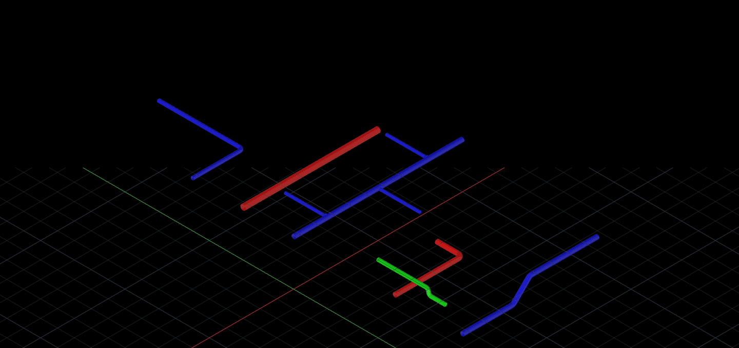
Every pipe and duct is a real 3D body

Plans show the axis, outline and insulation the way engineers draw them; the shaded 3D view shows true volumes. That is what clash detection and IFC export use — no separate model to keep in sync.

Heating flow and return pipes and a ventilation duct in shaded 3D

Clean DWG

No proxy objects. No lock-in.

Each part is a normal block on its system layer, with the engineering data attached as extended data. Colleagues without VectorMEP see, edit and plot the drawing normally, and the network is rebuilt from geometry when you open it again.

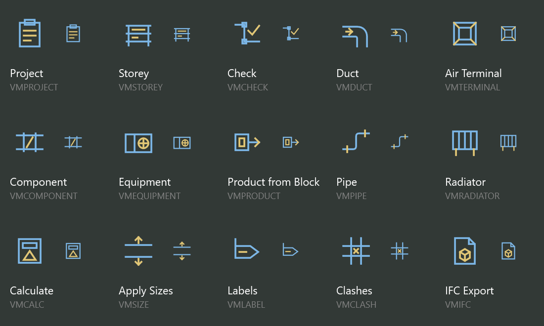
VectorMEP command icons: Project, Storey, Check, Duct, Air Terminal, Component, Equipment, Pipe, Radiator, Calculate, Apply Sizes, Labels, Clashes and IFC Export

On the roadmap

Sprinkler design and electrical systems are next. VectorMEP updates arrive with VectorCAD updates — no separate purchase.