Cables that know their circuit
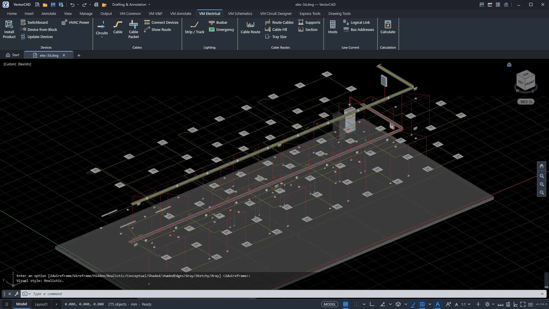
Each cable chains its devices back to the board; circuits, loads and protections are kept per board and checked with VMCIRCUITS.
Electrical · power, lighting & low current
Place switchboards, luminaires, sockets and detectors, chain them with cables, route the cables onto trays with their supports, check loads, voltage drop and short circuit — then draw the board's single-line schematic and the control pages from the same model.
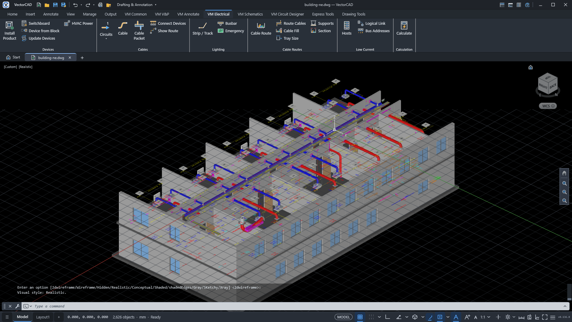
Each cable chains its devices back to the board; circuits, loads and protections are kept per board and checked with VMCIRCUITS.
Trays, ladders, trunking and conduit with fittings and supports; cables routed onto them, packets to the board and the tray fill checked.
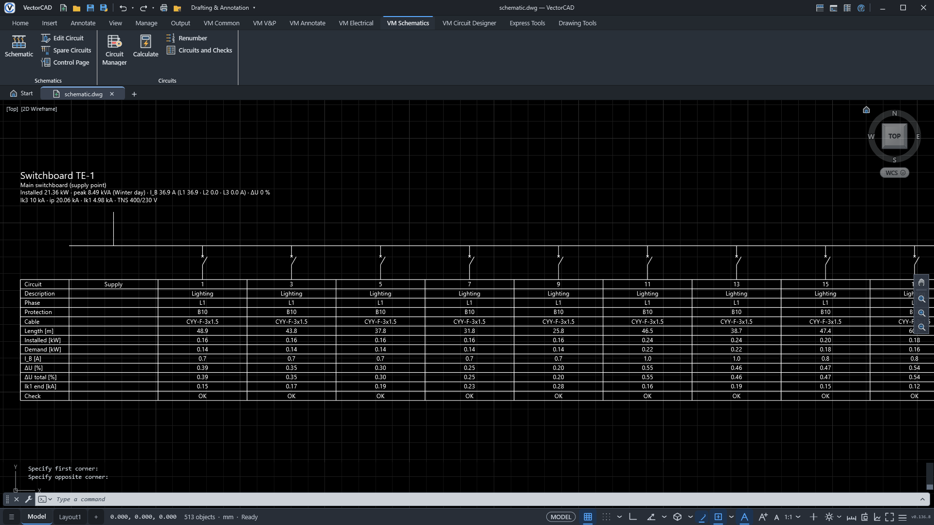
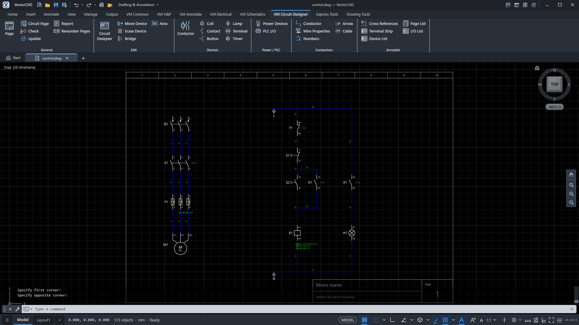
Single-line schematics of the boards and Circuit Designer control pages with cross references, terminals and device lists.
Luminaires in every room, sockets along the walls, the corridor trays and the cables of each circuit to the switchboards — in plan with their symbols, and in 3D.
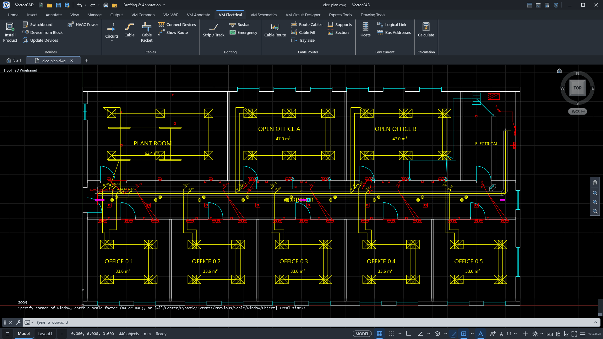
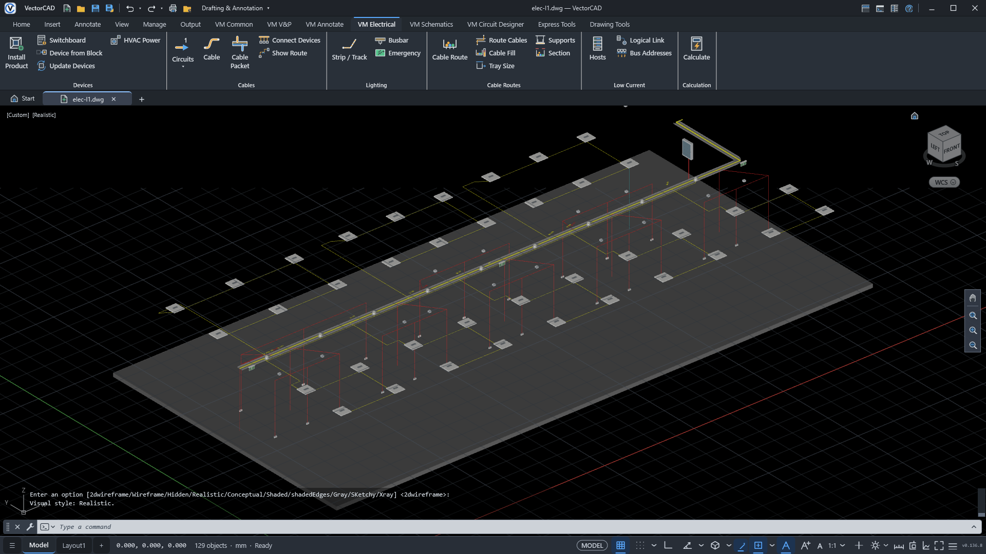
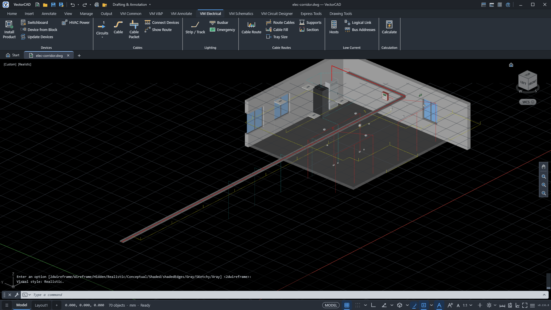
The main switchboard, the data rack and the fire alarm panel; the trays leaving the room along the corridor with their supports, and the cable packets up to the boards.
VMSCHEMA draws the switchboard's single-line schematic from its circuits; the Circuit Designer draws the air-handling unit's motor starter with its contactor, overload relay and push buttons, cross-referenced and numbered.
VMINSTALLPlace boards, luminaires, sockets, detectors and racks.
VMCABLE · VMTRAYChain the devices with cables and draw the trays.
VMCABLEROUTE · VMSUPPORTSRoute the cables onto the trays and add their supports.
VMCIRCUITS · VMELCALCCheck the circuits and calculate loads, voltage drop and short circuit.
VMSCHEMA · Circuit DesignerDraw the schematics and control pages from the model.
Free trial · 7 days
Download VectorCAD, start it and choose “Start 7-day trial”. You get the whole program — 2D, 3D, LISP, PDF and the complete VectorMEP module for HVAC, plumbing and electrical — with no card and no account. When the week is over, enter a license key and carry on with the same drawings.
7
days free on your PC
Download the free trialSee pricingWindows 10 / 11, 64-bit · 56 MB installer · opens your DWG files · one trial per PC